UML State Machine Diagram

The UML State Machine Diagram captures the different states of an object and how it transitions between them based on events.

Generate UML State Machine Diagram with AI Chatbot.

Instant State Machine Diagram Creation

Designing state-driven behavior becomes much easier with the AI chatbot. Instead of mapping every state and transition manually, you can describe how an object behaves in plain language. The chatbot instantly transforms your explanation into a clean and accurate UML State Machine Diagram. Whether you are outlining a UI component, a device controller, or a business object lifecycle, the AI provides a quick visual foundation that reflects your intended behavior.

The AI Chatbot can generate different diagrams according to your need in the chat.

Refine and Explore Through Conversation

After the initial diagram appears, you can keep improving it through simple, natural dialogue. Ask the AI to add guards, insert missing events, reorganize transitions, or introduce new states. Every adjustment updates the diagram instantly, helping you explore different behavioral patterns without redrawing anything. This conversational approach makes it easier to uncover edge cases, validate logic, and refine the object’s lifecycle with confidence.

Benefits of Creating State Machine Diagrams with the AI Chatbot

tick-icon-3.png

Converts natural-language descriptions into precise states, transitions, and events.

tick-icon-3.png

Ensures correct UML notation, including guards, triggers, and entry/exit actions.

tick-icon-3.png

Keeps complex diagrams readable by automatically arranging states and flows.

tick-icon-3.png

Allows rapid iteration—add new behaviors or restructure logic anytime.

tick-icon-3.png

Helps detect invalid, unreachable, or conflicting transitions through AI analysis.

tick-icon-3.png

Encourages clearer thinking by visualizing state-based logic early in design.

tick-icon-3.png

Maintains up-to-date behavioral documentation throughout development.

Examples of Generating UML State Machine Diagram

Use simple text prompts to generate this diagram in seconds. Here are a few examples to get you started:

3D Printing Job Workflow

State Machine Diagram example of 3D Printing Job Workflow

“Generate a detailed report describing the main states, their roles, and how the transitions occur between them. “

Digital Voting Platform

“Create a state machine diagram for a Digital Voting Platform.”

Automated Toll Collection System

State Machine Diagram example of Automated Toll Collection System

“Create a state machine diagram for an Automated Toll Collection System. “

What Is a UML State Machine Diagram?

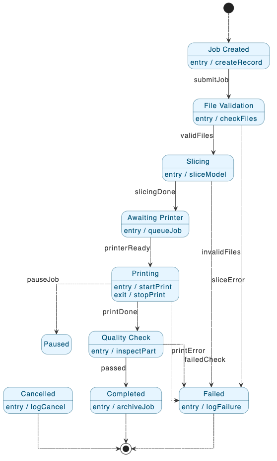
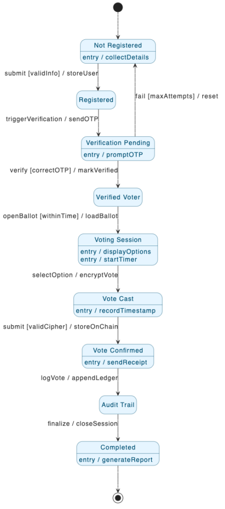
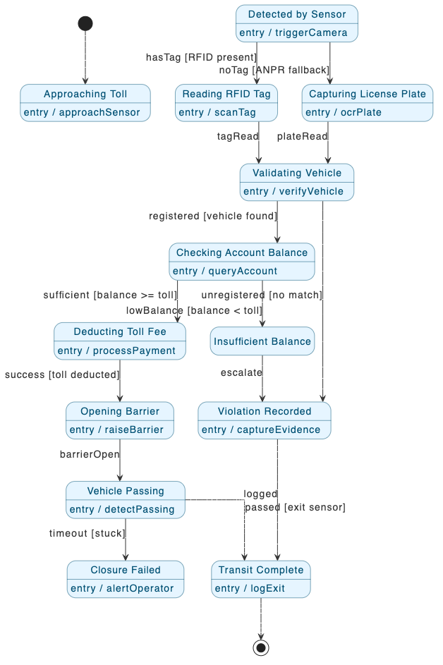
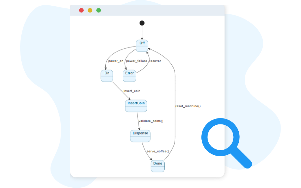
A UML State Machine Diagram models how a single object behaves over time. It illustrates the states an object can occupy and the events that cause it to transition from one state to another. This makes it ideal for systems where behavior depends heavily on what has happened before.

These diagrams help describe predictable, event-driven logic such as UI flows, device operations, protocol stages, and object lifecycles. By visualizing the sequence of states and transitions, teams gain a clearer understanding of complex behavior and can design systems that respond consistently and reliably.

Key Concepts of a State Machine Diagram

Key Concepts

State Machine Diagram

A State Machine Diagram describes how an object behaves by showing the different states it can be in and the transitions triggered by events or conditions. It is useful for modeling dynamic behavior, such as the lifecycle of an order, device, or process.

A complex state that references another state machine, allowing large models to be broken into manageable parts.

A final state, represented by a circle with a dot inside, showing where the object’s lifecycle or process terminates.

Merges multiple concurrent flows back into a single flow.

A pseudo-state that remembers the last active sub-state at all levels of nesting in a composite state.

State

Represents a situation during the life of an object when it satisfies some condition or performs an activity. Example: A “Payment Pending” state in an order system.

The starting point of the state machine, represented by a filled black circle. It indicates where the object begins its lifecycle.

Splits one flow into multiple concurrent flows, representing parallel states or activities.

A pseudo-state that remembers the last active sub-state within a composite state but does not remember nested sub-states.

A directed arrow that shows movement from one state to another, usually labeled with the triggering event or condition.

Ready to Revolutionize Your Workflow with AI?

Stop wrestling with tools. Embrace AI-powered visual modeling. Let our AI handle the visualization so you can focus on solving the bigger problems.

Scroll to Top