

Designing a Reliable Power Grid: AI-Powered SysML Internal Block Diagram of a Substation Transformer System
Designing a robust electrical power substation requires more than just components—it demands a clear understanding of how energy flows, how systems interact, and how failures are prevented. The complexity of power systems demands a modeling approach that is both precise and intuitive. Enter the Visual Paradigm AI Chatbot, which transforms abstract requirements into detailed, standards-compliant SysML Internal Block Diagrams through natural conversation.
From Concept to Clarity: An Interactive Design Journey
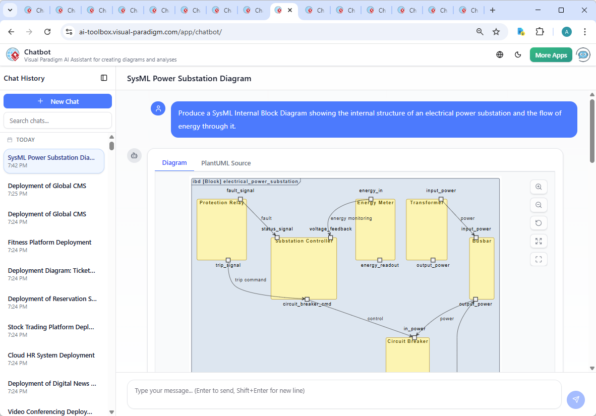
The journey began with a simple prompt: “Produce a SysML Internal Block Diagram showing the internal structure of an electrical power substation and the flow of energy through it.” Within moments, the AI Chatbot delivered a fully structured SysML diagram using PlantUML syntax, with clearly defined blocks, ports, and flow relationships. The system was not just visual—it was functional.
But the real value emerged in the conversation. After reviewing the initial output, the user asked: “Can you explain the role of the Voltage Regulator in maintaining stable output voltage within the substation?”
The AI responded with a detailed, technically accurate explanation—highlighting how the Voltage Regulator detects load fluctuations, adjusts output voltage, and communicates with the Substation Controller. This wasn’t just documentation; it was modeling intelligence in action.
When the user requested refinements—such as clarifying how fault signals trigger protective actions—the AI adapted the diagram and logic in real time, demonstrating its ability to function as a collaborative design partner. This iterative exchange, powered by the Visual Paradigm AI Chatbot, turned a static diagram into a living, evolving model of a real-world power system.
Visualizing the System: The Internal Block Diagram
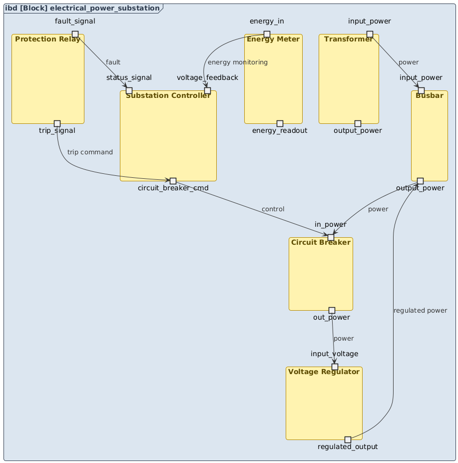
The final diagram captures the core architecture of a modern electrical power substation. It uses SysML’s Internal Block Diagram (IBD) notation to represent:
- Internal Structure: Each component (Transformer, Busbar, Circuit Breaker, etc.) is defined as a block with input and output ports.
- Energy Flow: Arrows labeled
powertrace the path from incoming high-voltage supply through the transformer, busbar, circuit breaker, and regulator before distribution. - Control and Feedback: Critical signals—such as
fault,trip command, andenergy monitoring—show how automation and protection systems respond in real time.
Decoding the Logic: Why IBD and How It Works
The choice of Internal Block Diagram (IBD) in SysML is essential for modeling complex systems like power substations. Unlike traditional diagrams, IBDs explicitly define:
- Composition: How components are structured internally and connected.
- Port-Based Interfaces: Each component exposes ports (e.g.,
input_power,regulated_output) that define how energy and signals are exchanged. - Flow Properties: The use of labeled flows (e.g.,
power,fault,trip command) makes the system’s behavior explicit and traceable.
For example:
Transformerreceives high-voltage input and outputs lower-voltage power to theBusbar.- The
Busbardistributes power to multiple downstream components, including theCircuit BreakerandVoltage Regulator. - The
Voltage Regulatoradjusts output based on feedback from theSubstation Controller, ensuring stable voltage under load changes. - The
Protection Relaymonitors for faults and sends atrip signalto the controller, which then commands the circuit breaker to isolate the faulty section.
This level of detail supports system verification, failure analysis, and compliance with engineering standards—making the IBD not just a diagram, but a design artifact.
Conversational Intelligence in Action
The real power of the Visual Paradigm AI Chatbot lies in its ability to act as a modeling consultant. During the session, the user didn’t just generate a diagram—they engaged in a dialogue that deepened understanding:
- When asked to explain the Voltage Regulator’s role, the AI provided a structured breakdown of its function, including load adaptation, protection, and integration with control systems.
- Follow-up requests like “Explain this branch” or “Refine the logic” were handled with precision, ensuring the model remained both accurate and educational.
- The AI didn’t just draw a picture—it taught the user how the system works, layering knowledge onto the visual.
This is what sets Visual Paradigm apart: it’s not a diagram generator. It’s a collaborative modeling environment where the AI learns from your questions and evolves the design with you.
Beyond SysML: A Unified Platform for All Modeling Needs
The Visual Paradigm AI Chatbot isn’t limited to SysML. It supports a full suite of modeling standards, including:
- UML: For software and system design.
- ArchiMate: For enterprise architecture and business process modeling.
- C4 Model: For software architecture visualization at different levels of abstraction.
- Org Chart, SWOT, PEST, Mind Maps, PERT, and more: For strategic planning, project management, and stakeholder alignment.
Whether you’re designing a smart grid, mapping business processes, or modeling a software system, the AI Chatbot adapts to your needs—delivering accurate, context-aware diagrams in seconds.
Conclusion: A Smarter Way to Model
Creating a high-fidelity SysML Internal Block Diagram of a power substation is no longer a time-consuming, manual task. With the Visual Paradigm AI Chatbot, it’s a dynamic, intelligent conversation—one that combines technical accuracy with real-time learning.
From concept to execution, the AI guides you through every step, ensuring clarity, correctness, and completeness. Whether you’re an electrical engineer, system architect, or enterprise planner, Visual Paradigm gives you the tools to design with confidence.
Ready to build your next system model? Start your conversation with the Visual Paradigm AI Chatbot today.