


UML Component Diagram
The UML Component Diagram outlines the organization and dependencies of components that form the system’s structure.
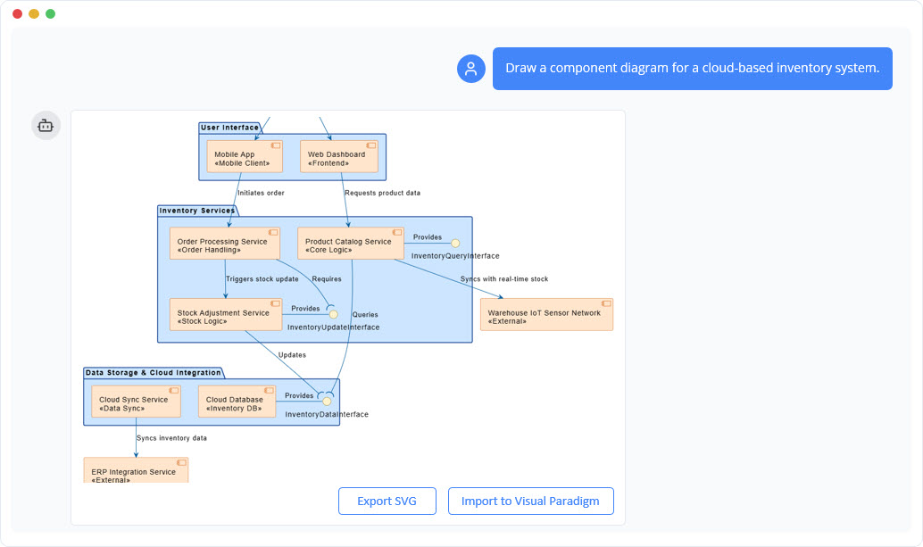
Instant Component Diagram Creation
With the AI chatbot, architectural modeling becomes much easier. Instead of manually arranging components, interfaces, and connectors, you can simply describe your system’s structure in plain language. The chatbot converts your explanation into a well-organized UML Component Diagram that highlights how parts of the system interact. Whether you are modeling a monolithic application or outlining a microservices layout, the AI quickly generates a clean visual foundation for your design work.
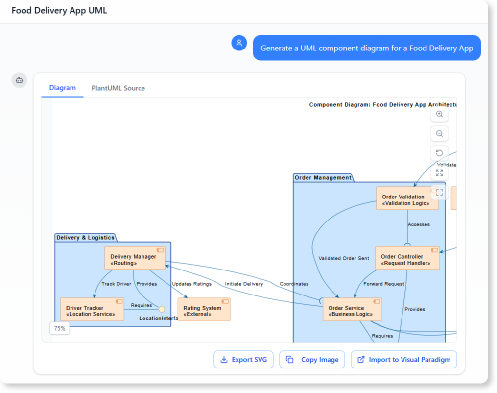
Refine and Explore Through Conversation
Once the first diagram is created, you can keep shaping it through simple conversation. Ask the AI to add new components, define interfaces, restructure dependencies, or group functionalities differently. The diagram updates instantly, letting you try multiple architectural ideas without redrawing anything. This conversational workflow makes it easy to improve modularity, clarify responsibilities, and experiment with different configurations until you reach the design that fits your goals best.

Benefits of Creating Component Diagrams with the AI Chatbot
Automatically applies correct UML notation for components, ports, interfaces, and connectors.
Speeds up architectural planning by converting natural language into structured diagrams.
Makes refinement easy—adjust components, add dependencies, or reorganize modules in seconds.
Helps ensure modularity by visualizing provided and required interfaces clearly.
Detects issues like tight coupling or circular dependencies through conversational analysis.
Keeps architectural documentation accurate and up-to-date throughout development.
Examples of Generating UML Component Diagram
Use simple text prompts to generate this diagram in seconds. Here are a few examples to get you started:
Social Media Platform
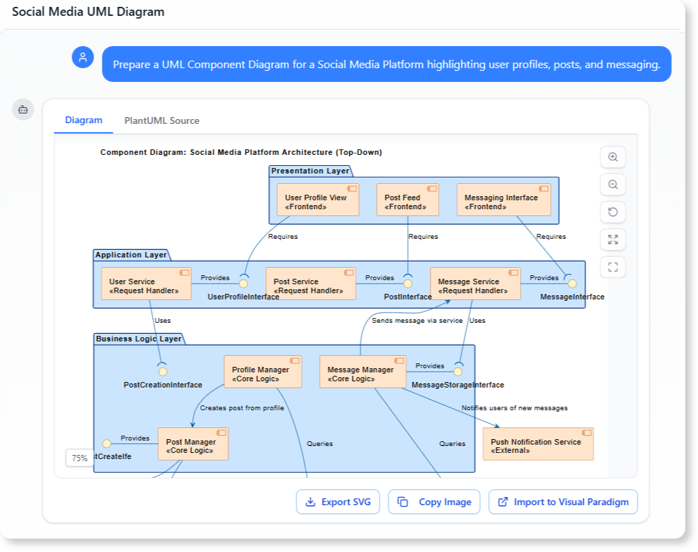
“Prepare a UML Component Diagram for a Social Media Platform highlighting user profiles, posts, and messaging.”
Hospital Management System
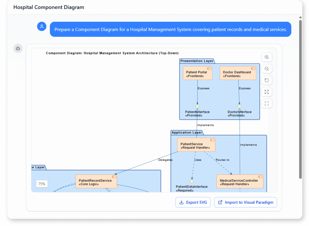
“Prepare a UML Component Diagram for a Hospital Management System covering patient records and medical services.”
What Is a UML Component Diagram?
A UML Component Diagram shows the high-level physical structure of a software system. It captures how components—such as services, modules, and libraries—are organized and how they communicate with one another through interfaces. This diagram focuses on modularity, helping teams break large systems into clear, manageable building blocks.
Component diagrams are especially useful during architectural planning and system documentation. By illustrating which functionalities are provided, which dependencies exist, and how components interact, they help teams maintain clean boundaries and design systems that are easier to build, extend, and maintain.
Key Concepts
Component Diagram
A component diagram is a UML diagram that models the software architecture of a system. It shows the components that make up the system, their provided/required interfaces, and the relationships between them.
Provided Interface
A Provided Interface defines the set of operations or services that a component offers to others. It specifies how other components can interact with it. Visually, it is represented as a lollipop (circle) symbol connected to the component.
Example: A “Payment Processor” component may have a required interface for “Customer Data Service” to access customer information.
Package
A package groups related components, interfaces, or other elements into a namespace. It helps structure complex systems into manageable layers or modules.
Realization
A realization shows that a component implements or fulfills the contract defined by an interface. It is drawn as a dashed line with a hollow triangle pointing to the interface.
Component
A component represents a modular and replaceable part of the system that encapsulates implementation and exposes functionality through interfaces. Examples include services, modules, or subsystems. Components are drawn as rectangles with the keyword <<component>> or a small tabbed icon.
Required Interface
A Required Interface represents the set of operations or services that a component needs from others to function. It defines external dependencies — what the component expects to be provided by another component or system. In diagrams, it is typically shown as a half circle (socket) attached to the component.
Example: A “Customer Data Service” component provides an interface for retrieving and updating customer records, which can be used by other components like “Payment Processor” or “Order Management.”
Dependency
A dependency indicates that one component relies on another (for example, a web application component depending on an authentication service). It is drawn as a dashed arrow pointing to the component being depended on.
Association
An association represents a communication or connection between components, showing that they can interact at runtime. Unlike dependency (which shows reliance), association emphasizes an established link.
Ready to Revolutionize Your Workflow with AI?
Stop wrestling with tools. Embrace AI-powered visual modeling. Let our AI handle the visualization so you can focus on solving the bigger problems.