UML Sequence Diagram

The UML Sequence Diagram visualizes the flow of messages between objects, showing how processes interact over time.

Generate UML Sequence Diagram with AI Chatbot.

Instant Sequence Diagram Generation

With the AI chatbot, creating a sequence diagram becomes as simple as describing how your scenario unfolds. Just explain the interaction in natural language, and the chatbot instantly transforms it into a clear, time-ordered diagram. Lifelines, messages, replies, and interaction fragments are all arranged automatically, giving you a polished visualization without manual formatting or layout effort.

The AI Chatbot can generate different diagrams according to your need in the chat.

Discuss and Refine Your Interaction Flow

The chatbot does more than produce a diagram; it helps you shape the logic behind it. You can ask it to add alternative paths, convert synchronous calls to asynchronous ones, or highlight any unclear steps in the flow. Every adjustment happens through conversation, allowing you to refine the interaction until it matches exactly how the system should behave.

Benefits of Creating Sequence Diagrams with the AI Chatbot

tick-icon-3.png

Translate written scenarios into structured diagrams instantly.

tick-icon-3.png

Automatically organize lifelines, messages, and fragments for readability.

tick-icon-3.png

Explore different paths or logic variations through natural conversation.

tick-icon-3.png

Identify interaction bottlenecks or redundant steps with AI feedback.

tick-icon-3.png

Save time on diagram formatting and focus on system behavior design.

Examples of Generating UML Sequence Diagram

Use simple text prompts to generate this diagram in seconds. Here are a few examples to get you started:

Event Ticket Verification System

UML Sequence Diagram Example of Music Festival Event Ticket Verification System

“Show a sequence diagram for a Music Festival Event Ticket Verification System. “

Crowdfunding Donation Platform

UML Sequence Diagram Example of Crowdfunding Donation Platform

“Create a sequence diagram for a Crowdfunding Donation Platform.”

Telemedicine Video Consultation Platform

UML Sequence Diagram Example of Telemedicine Video Consultation Platform

“Generate a sequence diagram for a Telemedicine Video Consultation Platform.”

What is a UML Sequence Diagram

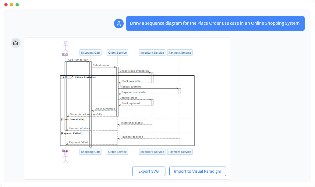
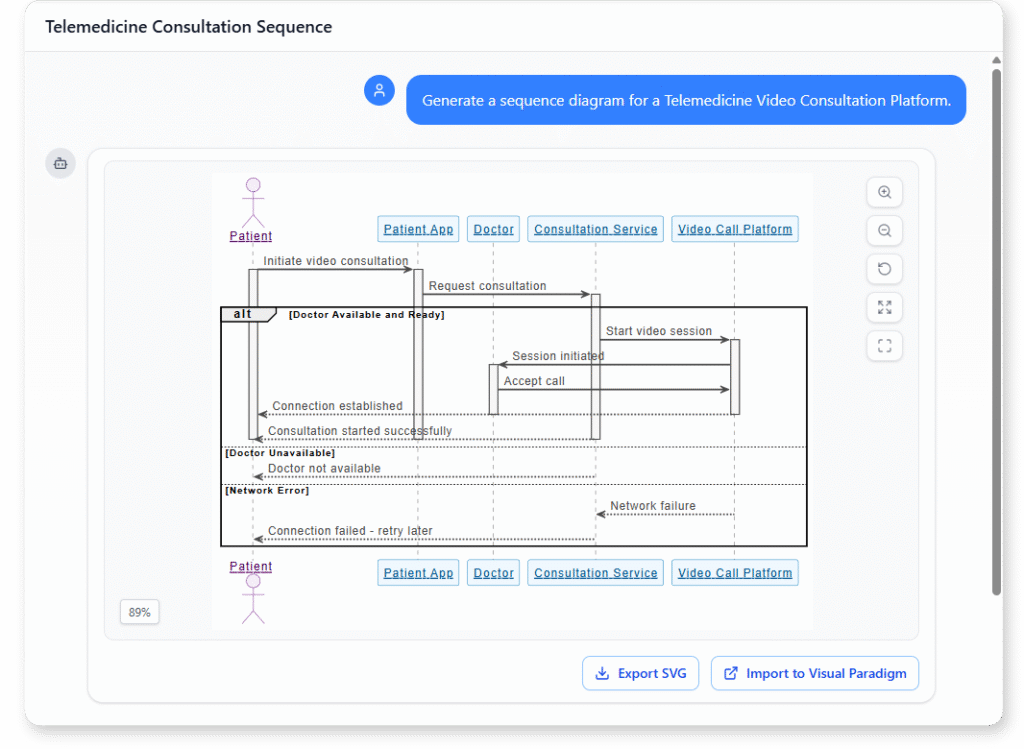
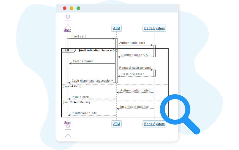
A UML Sequence Diagram shows how different parts of a system communicate over time. It captures the order of messages between objects, making it easy to understand the flow of interactions within a single scenario.

Sequence diagrams help you visualize system behavior step-by-step, revealing how components work together to complete a task. This time-based structure makes them valuable for clarifying logic, validating requirements, and analyzing dynamic processes.

Key Concepts of a Sequence Diagram

Key Concepts

Sequence Diagram

sequence diagram is a UML diagram that models the flow of interactions over time between actors and system components. It shows how objects or components exchange messages in a particular scenario, step by step.

message is an arrow between lifelines, showing communication such as a method call, signal, or data transfer. Messages can be synchronous (waiting for a response), asynchronous, or return messages.

The loop fragment models repetition of a sequence of messages, similar to a “for” or “while” loop in programming. It includes a guard condition that controls the repetition.

The alt (alternative) fragment models conditional flows — “if/else” logic. It contains multiple sections, each with a guard condition, and only one section executes at runtime.

Actor

An actor represents a user or external system that interacts with the system. In a sequence diagram, actors are drawn as stick figures placed on the left or right side of the diagram.

lifeline represents an individual participant in the interaction, shown as a vertical dashed line. It indicates the object’s presence over time.

Types of lifelines:

  • General lifeline: Represents any object or component.

  • Boundary lifeline: Represents an interface to external actors (e.g., UI or API).

  • Control lifeline: Represents logic or control behavior (e.g., a controller class).

  • Entity lifeline: Represents a data object or persistent entity (e.g., a record).

  • Database lifeline: Represents a database, often shown with the cylinder symbol.

The opt (optional) fragment models behavior that may or may not occur depending on a condition. It’s like a simplified “if” without an “else.”

Ready to Revolutionize Your Workflow with AI?

Stop wrestling with tools. Embrace AI-powered visual modeling. Let our AI handle the visualization so you can focus on solving the bigger problems.

Scroll to Top