

As software systems grow, the key to avoiding a tangled, unmaintainable mess—a “big ball of mud”—is a modular design. The UML Component Diagram is the primary blueprint for this style of architecture. It provides a high-level, structural view of a system, illustrating its physical components and their relationships. While essential for building robust software, creating these diagrams has traditionally been a meticulous process. Today, an AI assistant revolutionizes this task, transforming architectural design from a static drawing exercise into an intelligent, dynamic, and collaborative conversation.
This guide explains the fundamentals of Component Diagrams and how AI can help you design better, more modular systems.
What is a UML Component Diagram?
A Component Diagram models the physical aspects of a system, visualizing how a complex system is broken down into smaller, manageable, and replaceable components, and how these components are wired together.
Core Components
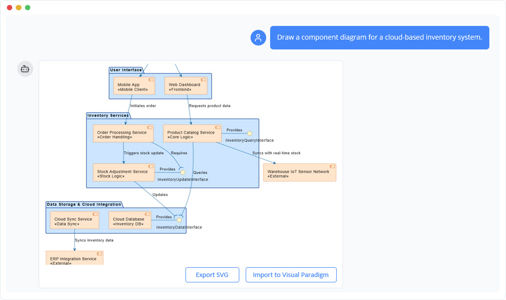
- Component: A modular, replaceable, and self-contained part of a system (e.g., a library, a service, an executable). It is represented by a rectangle with a small two-pronged icon.
- Interface: A formal contract through which components interact, crucial for achieving loose coupling.
- Provided Interface: The services a component offers. Shown using a “lollipop” notation (a line with a circle).
- Required Interface: The services a component needs from others. Shown using a “socket” notation (a line with a semi-circle).
- Dependency: A relationship where a change in one component may affect another. It is shown as a dashed arrow from the client to the supplier.
- Port: An explicit interaction point on the boundary of a component, shown as a small square.
- Assembly Connector: The “wire” that connects a required interface of one component to a provided interface of another.
The goal is to create a map of the system that emphasizes modularity and separation of concerns—the cornerstones of good software architecture.
Why Use AI for Component Diagrams?
Manually creating architectural diagrams can be a significant challenge in a fast-moving project. An AI co-pilot eliminates this friction and adds powerful new capabilities.
- Instant Architecture Generation: Describe a system’s structure in natural language, and the AI will instantly generate a syntactically correct and visually clean component diagram.
- Master Architectural Notation: The “lollipop and socket” notation is powerful but can be confusing. The AI handles this perfectly every time. You define the contracts; the AI visualizes them correctly.
- Explore Design Alternatives with Ease: Good architecture involves evaluating trade-offs. An AI makes it trivial to explore different options. Rapidly generate diagrams for monolithic, microservices, and SOA patterns to visually compare them side-by-side.
- Intelligent Analysis: An AI can go beyond just drawing. Ask it to analyze your diagram for architectural flaws: “Are there any circular dependencies between my components?” This moves the AI from a drawing tool to an architectural advisor.
Common Use Cases for Component Diagrams
Component diagrams are a powerful asset in real-world software development.
- Designing Microservices and SOA: Use them as the master plan for a microservices architecture, defining the service boundaries and the API contracts between them.
- Understanding Legacy Systems: Document a large, complex application by modeling its main logical blocks as components, creating an invaluable high-level map for new developers and refactoring efforts.
- Planning System Refactoring: Model the “as-is” and “to-be” architectures to clearly visualize the impact of a refactoring (e.g., extracting a new service from a monolith).
- Visualizing Third-Party Integrations: Model how your application interacts with external systems (like Stripe or Salesforce) through abstract interfaces, promoting a loosely coupled design.
How to Generate Component Diagrams with AI: Example Prompts
Communicating your architectural vision to the AI requires clear language.
- Basic Components: “Create a component diagram with three components: ‘User Interface’, ‘Business Logic’, and ‘Data Access’.”
- Dependencies: “Show a dependency from ‘User Interface’ to ‘Business Logic’.”
- Interfaces: “The ‘Business Logic’ component provides an interface named ‘IService’. The ‘User Interface’ component requires the ‘IService’ interface.”
- Connections: “Connect the required interface of ‘User Interface’ to the provided interface of ‘Business Logic’ using an assembly connector.”
- Analysis: “Review this component diagram. Does it follow the principles of a layered architecture?”
A Modern Workflow for Software Architecture
Integrate AI-powered diagramming into your team’s core practices.
- Live Architectural Design Sessions: Use the AI live in design meetings to translate sketches and ideas into formal component diagrams in real-time.
- The Architectural Blueprint: Generate the canonical component diagram for your project to serve as the “source of truth” for its high-level structure.
- Onboarding and Knowledge Sharing: Use the component diagram to give new developers a high-level map of the system before they dive into the code.
- Continuous Architectural Review: Because AI makes updates so easy, the component diagram can be kept in sync with the evolving codebase, ensuring it remains an accurate and valuable resource.
Conclusion
The UML Component Diagram is an essential tool for designing software that is built to last. By pairing this powerful modeling technique with an intelligent AI assistant, we supercharge the architectural design process. The AI removes the tedious friction of manual drawing, ensures notational correctness, and even acts as an analytical partner, freeing human architects to focus on creating elegant, robust, and scalable systems.