


Entity Relationship Diagram (ERD)
An Entity Relationship Diagram (ERD) models database structures by visually mapping entities, attributes, primary and foreign keys, and cardinalities between tables.
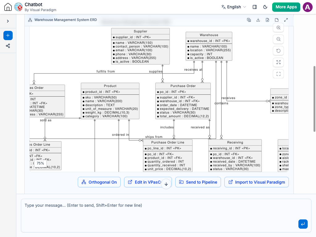
Instant ERD Creation
Designing database schemas and visualizing table relationships doesn’t have to require manual table setup or complex SQL modeling tools. Instead of manually drawing tables, setting up data types, and linking connector lines, you can simply describe your database requirements to the AI Chatbot in plain language.
The system translates your description into a clean, normalized ERD. It automatically identifies core entities, creates fields with appropriate data types, assigns primary/foreign keys, and sets up relationship cardinalities. Whether you are building an e-commerce backend or an HR management system, you get an accurate database blueprint in seconds.
Refine Database Schemas Through Conversation
Updating table structures and tweaking relationships is effortless using plain language. You can easily modify your database design directly inside the chat interface by entering requests like:
Add entities and fields: “Add an Orders table with order_date, total_amount, and status, and link it to the Customer table.”
Modify keys and constraints: “Set email in the Users table as a unique constraint and make user_id a foreign key in User_Profiles.”
Adjust relationship cardinalities: “Change the relationship between Customer and Address from one-to-many to many-to-many through a junction table.”
The diagram updates instantly, automatically realigning tables, foreign key markers, and connector lines so your schema remains clean and structured.


Standard Database Notation: Renders industry-standard notations like Crow’s Foot or UML to clearly represent tables and fields.
Automated Key & Cardinality Mapping: Automatically infers primary keys, foreign keys, and one-to-one, one-to-many, or many-to-many links.
Faster Backend Planning: Helps developers and database administrators plan database schemas before writing DDL code or migrations.
Clear Architecture Documentation: Serves as a single source of truth for engineering teams, keeping data models synchronized across project cycles.
Examples of Generating ERDs
Use simple text prompts to generate this diagram in seconds. Here are a few examples to get you started:
E-Commerce Database Schema
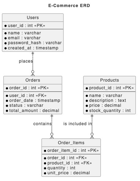
“Generate an ERD for an e-commerce database with Users, Orders, Order_Items, and Products, including primary keys, foreign keys, and 1-to-many links.”
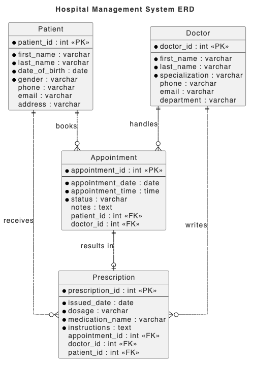
“Create an ERD for a hospital management system mapping Patients, Doctors, Appointments, and Prescriptions with foreign key relationships.”
School Learning Management Schema
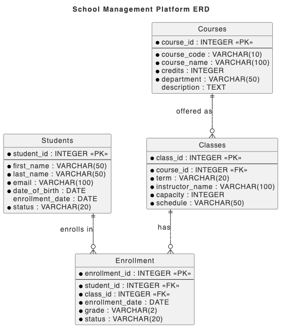
“Create a relational database ERD for a school management platform showing Students, Courses, Classes, and an Enrollment junction table for N:M mapping.”
What is an Entity Relationship Diagram?
An Entity Relationship Diagram (ERD) is a structural diagram that illustrates how entities (such as people, objects, or concepts) relate to one another within a database system. ERDs use specific symbols to define entities as tables, attributes as columns, and lines to represent relationships and cardinalities between tables.
ERDs are essential for software engineers, database administrators, and system architects to design relational database schemas, optimize data structures, and communicate backend architecture to development teams.
Key Concepts
Entities (Tables)
Core objects or data concepts stored in the database, represented as rectangular table blocks.
Attributes (Columns / Fields)
Properties or data points that describe an entity, along with their specific data types (e.g., VARCHAR, INT, BOOLEAN).
Primary Key (PK)
A unique identifier field that uniquely distinguishes each record within a table.
Foreign Key (FK)
A field in one table that references the primary key of another table to establish a relationship.
Cardinality
Notation (such as Crow’s Foot) that defines the numerical relationship between entities (e.g., 1:1, 1:N, N:M).
Ready to Model Your Database Schema with AI?
Stop manually drawing database tables and connecting key lines. Turn your data requirements into clear entity relationship diagrams instantly through simple conversation.